
How to build a polygraph prototype

Polygraph and Truth Machine(s)
Dependencies
Arduino v - 1.8 Processing v -
We have x2 different types of sensors that can be turned into different polygraphs using different Things form groups around which sensor you would like to use
- Electrodermal activity(EDA AKA skin sweat)
- Heartbeat
Electrodermal Activity
Electrodermal activity (EDA) is the property of the human body that causes continuous variation in the electrical characteristics of the skin.The traditional theory of EDA holds that skin resistance varies with the state of sweat glands in the skin. Sweating is controlled by the sympathetic nervous system, and skin conductance is an indication of psychological or physiological arousal. If the sympathetic branch of the autonomic nervous system is highly aroused, then sweat gland activity also increases, which in turn increases skin conductance. In this way, skin conductance can be a measure of emotional and sympathetic responses
The scientific study of EDA began in the early 1900s. One of the first references to the use of EDA instruments in psychoanalysis is the book by C. G. Jung entitled Studies in Word Analysis, published in 1906.[11][12] Jung and his colleagues used the meter to evaluate the emotional sensitivities of patients to lists of words during word association.[13][14] Jung was so impressed with EDA monitoring, he allegedly cried, “Aha, a looking glass into the unconscious!”[15] Jung described his use of the device in counseling in his book, Studies in Word Association, and such use has continued with various practitioners.[16]
- x1 Arduino uno
- x1 Breadboard
- x1 10k resistor
- Tin foil and tape
- x3 LEDS (optional)
Step 1 Prepare Contacts
GSR machines require an even and consistent connection to the skin in order to function properly. To keep surface area and pressure constant, we will make x2 tin foil electrodes to wrap around two fingers of the interrogated subject.
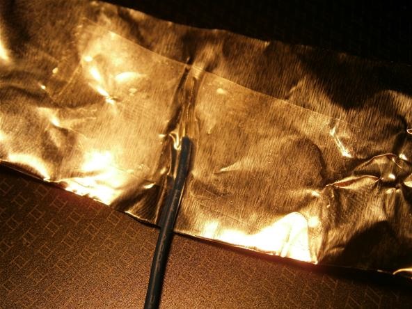
Begin by taping the exposed end of a wires to a sheet of foil.
Prepare the contact points onto the tin foil with Sellotape
Step 2 Make Circuit
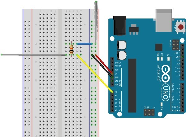
the Grey wires is going out to your two contact points
Step 3 Load the Code
copy this into your arduino sketch. Run verify then upload to sketch if it throws no errors.
void setup() {
// initialize the serial communication:
Serial.begin(9600);
}

void loop() {
// send the value of analog input 0:
Serial.println(analogRead(A0));
// wait a bit for the analog-to-digital converter
// to stabilize after the last reading:
delay(100);
}
We can just use the example “Graph” code that comes with the Arduino software. Navigate to tools>Serial Plotter> and you should see the data coming in from A0 in real time on a graph.
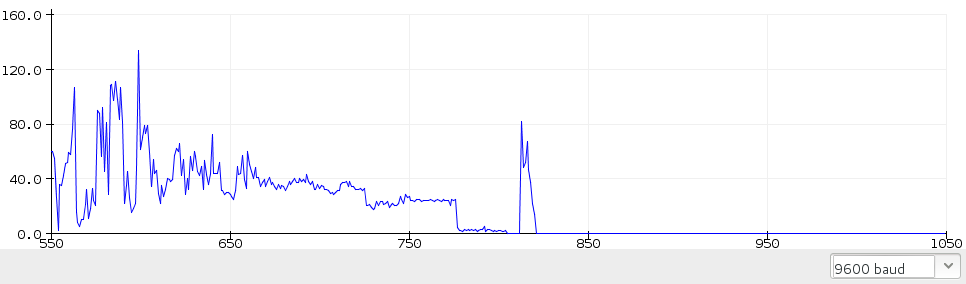
If you do not have the Processing application, it is free to download here. Copy and paste the processing code from the Arduino example into the processing application. The processing window should look familiar as the Arduino application is based off of it. Run the processing program. A graph should pop up. The height of the graph line represents the conductivity of your skin. The higher the line, the higher the conductivity, the higher likelihood that you are lying. this guide is helpful - https://mad-science.wonderhowto.com/how-to/diy-polygraph-machine-detect-lies-with-tin-foil-wire-and-arduino-0134599/
Step 4 Attach LEDS (optional)
Once you have a steady signal coming through you may want to attach LEDS to indicate when the polygraph thinks that the subject is telling the truth.
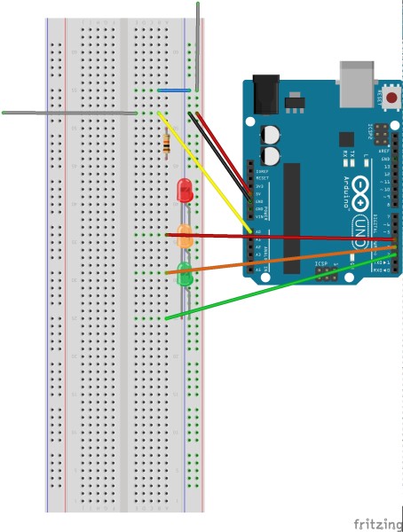
Use the code below to configure your LEDS (you may need to change some variables)
/*comments
2 is green
3 is yellow
4 is red
*/
void setup()
{
  Serial.begin(9600);
  pinMode(2, OUTPUT);
  pinMode(3, OUTPUT);
  pinMode(4, OUTPUT);
  digitalWrite(2, HIGH);
  delay(500);
  digitalWrite(3, HIGH);
  delay(500);
  digitalWrite(4, HIGH);
  delay(500);
}

void loop()
{
  if (analogRead(A0) > 30)
  {
    digitalWrite(4, HIGH);
  }
  else
  {
    digitalWrite(4, LOW);
  }
  if (analogRead(A0) > 20)
  {
    digitalWrite(2, HIGH);
  }
  else
  {
    digitalWrite(2, LOW);
  }
  if (analogRead(A0) > 10)
  {
    digitalWrite(3, HIGH);
  }
  else
  {
    digitalWrite(3, LOW);
  }

  Serial.println(analogRead(A0));
  delay(20);
}
❤️ Heart Detector ❤️
- x1 Arduino uno
- x1 pulse sensor
- PulseSensor Playground library
Step 1 - Wire up the Pulse Sensor to the Arduino
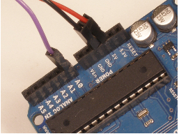
- RED wire = +3V to +5V
- BLACK wire = GND
- PURPLE wire = Signal
Step 2 - Install PulseSensorPlayground library for Arduino
- To install the PulseSensor Playground Library, in Arduino, to go ‘'’Sketch > Include Library > Manage Library…’’’
- In the Library Manager: Search for and Select “PulseSensor.com
- Install or update to the lastest version.+1
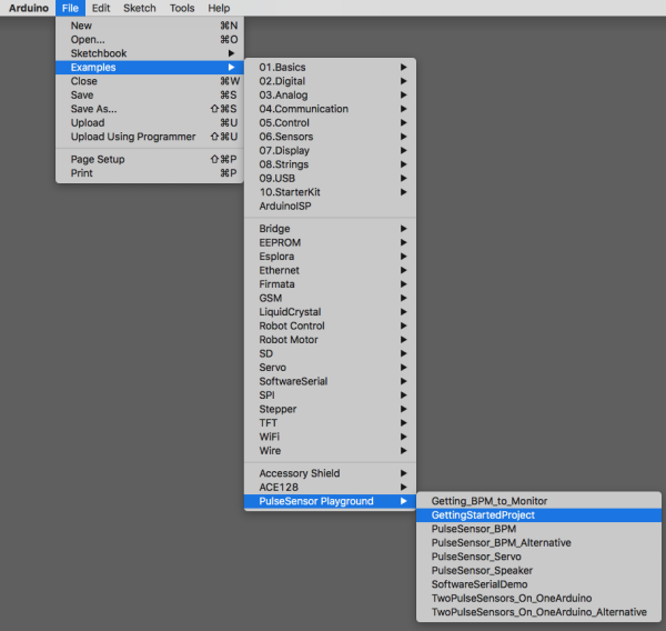
- Once this library is installed you will see our examples in Arduino’s dropdown! To select an example project, go to:
Get the latest Arduino software here [https://github.com/WorldFamousElectronics/PulseSensorPlayground] (https://github.com/WorldFamousElectronics/PulseSensorPlayground) Follow the README guide to get set up, or follow this Getting Started Tutorial For Arduino IDE download: https://www.arduino.cc/en/Main/Software
Connect the Pulse Sensor to: +V (red), Ground (black), and Analog Pin 0 (purple) on your favorite Arduino, or Arduino compatible device, Then find the Getting Started sketch by clicking File > Examples > PulseSensor Playground > A_StarterProject_and_SignalTester
Step 3 - Connect the sensor to the body
The pulse sensor works by being attached to either earlobe or end of finger. If you’re having trouble seeing a heartbeat, make sure that you are using ‘Goldilocks’ pressure on the Pulse Sensor: Not too hard, not too soft. Squeezing the Pulse Sensor too hard against your skin will make the heartbeat go away, and not enough pressure will cause too much noise to creep in! If this code is reading too many Beats Per Minute, or you are getting lots of noise, try adjusting the Threshold setting. The Threshold variable tells Arduino when to find a pulse that is legit. Adjust the Threshold value (noted above with arrows). The Threshold can be any number between 0-1024, but try adjusting by steps of 5 or 10. Decreasing the Threshold increases the sensitivity. Increasing the Threshold decreases the sensitivity.
Step 4 - attach led (optional)
pro tip - you can also just stick an LED directly into pin 13 and ground! This is a helpful guide for getting started with the PulseSensor https://docs.google.com/document/d/1d8EwDcXH1AZpIpEnrET28EBgStrbkbppxjQZcNRAlkI/edit