
Sensor IoT Workshop - Heart Rate
❤️ Heart Detector for Arduino ❤️
- x1 Arduino uno
- x1 pulse sensor
- PulseSensor Playground library
Step 1 - Wire up the Pulse Sensor to the Arduino
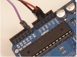
- RED wire = +3V to +5V
- BLACK wire = GND
- PURPLE wire = Signal
Step 2 - Install PulseSensorPlayground library for Arduino
- To install the PulseSensor Playground Library, in Arduino, to go ‘'’Sketch > Include Library > Manage Library…’’’
- In the Library Manager: Search for and Select “PulseSensor.com
- Install or update to the lastest version.+1
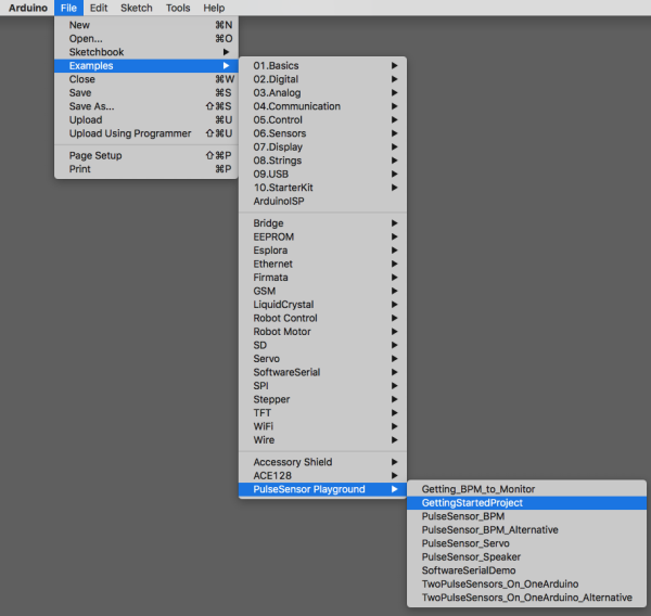
- Once this library is installed you will see our examples in Arduino’s dropdown! To select an example project, go to:
Get the latest Arduino software here [https://github.com/WorldFamousElectronics/PulseSensorPlayground] (https://github.com/WorldFamousElectronics/PulseSensorPlayground) Follow the README guide to get set up, or follow this Getting Started Tutorial For Arduino IDE download: https://www.arduino.cc/en/Main/Software
Connect the Pulse Sensor to: +V (red), Ground (black), and Analog Pin 0 (purple) on your favorite Arduino, or Arduino compatible device, Then find the Getting Started sketch by clicking File > Examples > PulseSensor Playground > A_StarterProject_and_SignalTester
Step 3 - Connect the sensor to the body
The pulse sensor works by being attached to either earlobe or end of finger. If you’re having trouble seeing a heartbeat, make sure that you are using ‘Goldilocks’ pressure on the Pulse Sensor: Not too hard, not too soft. Squeezing the Pulse Sensor too hard against your skin will make the heartbeat go away, and not enough pressure will cause too much noise to creep in! If this code is reading too many Beats Per Minute, or you are getting lots of noise, try adjusting the Threshold setting. The Threshold variable tells Arduino when to find a pulse that is legit. Adjust the Threshold value (noted above with arrows). The Threshold can be any number between 0-1024, but try adjusting by steps of 5 or 10. Decreasing the Threshold increases the sensitivity. Increasing the Threshold decreases the sensitivity.
Step 4 - attach led (optional)
pro tip - you can also just stick an LED directly into pin 13 and ground! This is a helpful guide for getting started with the PulseSensor https://docs.google.com/document/d/1d8EwDcXH1AZpIpEnrET28EBgStrbkbppxjQZcNRAlkI/edit
### ❤️ Heart Detector for Raspberry Pi ❤️
 This guide will show you an easier way to install and use new Python code to talk to the MCP3008 ADC.
The MCP3008 datasheet is also an important resource to skim and have handy.
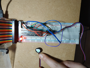
Wiring
The MCP3008 connects to the Raspberry Pi using a SPI serial connection. You can use either the hardware SPI bus, or any four GPIO pins and software SPI to talk to the MCP3008. Software SPI is a little more flexible since it can work with any pins on the Pi, whereas hardware SPI is slightly faster but less flexible because it only works with specific pins. If you aren’t sure which to use I recommend software SPI as it’s easier to setup.
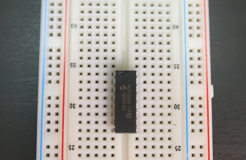
Before you can wire the chip to the Pi you first need to place it into a breadboard. If you haven’t used bare DIP chips like the MCP3008 before you want to press it into the breadboard so its legs straddle the empty channel in the middle of the breadboard. This way you can access each of the legs of the chip from the breadboard.
Note that the orientation of the chip matters! Be sure to place it with the half circle indention and dot towards the top. See the photo below for an example:
Software SPI
To connect the MCP3008 to the Raspberry Pi with a software SPI connection you need to make the following connections:
- MCP3008 VDD to Raspberry Pi 3.3V
- MCP3008 VREF to Raspberry Pi 3.3V
- MCP3008 AGND to Raspberry Pi GND
- MCP3008 DGND to Raspberry Pi GND
- MCP3008 CLK to Raspberry Pi pin 18
- MCP3008 DOUT to Raspberry Pi pin 23
- MCP3008 DIN to Raspberry Pi pin 24
- MCP3008 CS/SHDN to Raspberry Pi pin 25
Note that you can swap the MCP3008 CLK, DOUT, DIN, and CS/SHDN pins to any other free digital GPIO pins on the Raspberry Pi. You’ll just need to modify the example code to use your pins.
Library Install
After you’ve wired the MCP3008 to the Raspberry Pi with either the software or hardware SPI wiring you’re ready to install the Adafruit MCP3008 Python library.
You can install the library from the Python package index with a few commands, or you can install the library from its source on GitHub. Pick one of these options below. If you aren’t sure I recommend installing from source on GitHub because it will also download examples to use the library.
Note that before you install the library your Raspberry Pi must be connected to the internet through a wired or wireless network connection.
Install dependencies
sudo apt-get update
sudo apt-get install build-essential python-dev python-smbus git
cd ~
git clone https://github.com/adafruit/Adafruit_Python_MCP3008.git
cd Adafruit_Python_MCP3008
sudo python setup.py install
Edit the code
nano simpletest.py
# Software SPI configuration:
CLK  = 18
MISO = 23
MOSI = 24
CS   = 25
mcp = Adafruit_MCP3008.MCP3008(clk=CLK, cs=CS, miso=MISO, mosi=MOSI)

# Hardware SPI configuration:
# SPI_PORT   = 0
# SPI_DEVICE = 0
# mcp = Adafruit_MCP3008.MCP3008(spi=SPI.SpiDev(SPI_PORT, SPI_DEVICE))
The example will print out a table with all of the ADC channels and their values. Every half second a new row will be printed with the latest channel values. For example you might see output like:
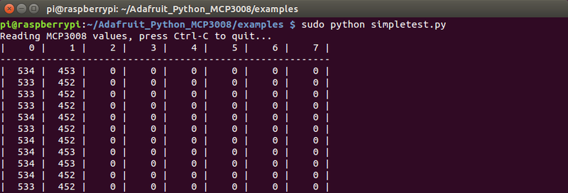
Once you have a signal coming in from the ADC you can begin to develop the code to do different things, like turn on an LED for every hear beats
e.g.
The code below takes an average reading and flashes an LED (on GPIO 2) when it detects a heartbeat
# Simple example of reading the MCP3008 analog input channels
# Author: Tony DiCola
# License: Public Domain
import time
# Import SPI library (for hardware SPI) and MCP3008 library.
import Adafruit_GPIO.SPI as SPI
import Adafruit_MCP3008
import RPi.GPIO as GPIO           # import RPi.GPIO module


GPIO.setmode(GPIO.BCM)            # choose BCM or BOARD
GPIO.setup(2, GPIO.OUT) # set a port/pin as an output

# Software SPI configuration:
CLK  = 18
MISO = 23
MOSI = 24
CS   = 25
mcp = Adafruit_MCP3008.MCP3008(clk=CLK, cs=CS, miso=MISO, mosi=MOSI)

MAX_HISTORY = 250

# Maintain a log of previous values to
# determine min, max and threshold.
history = []

print('Press Ctrl-C to quit...')
while True:
    # Grab the difference between channel 0 and 1 (i.e. channel 0 minus 1).
    # Note you can specify any value in 0-7 to grab other differences:
    #  - 0: Return channel 0 minus channel 1
    #  - 1: Return channel 1 minus channel 0
    #  - 2: Return channel 2 minus channel 3
    #  - 3: Return channel 3 minus channel 2
    #  - 4: Return channel 4 minus channel 5
    #  - 5: Return channel 5 minus channel 4
    #  - 6: Return channel 6 minus channel 7
    #  - 7: Return channel 7 minus channel 6
    v = mcp.read_adc(1)
    # print('Channel 1: {0}'.format(v))
    # time.sleep(0.5)
    history.append(v)

    # Get the tail, up to MAX_HISTORY length
    history = history[-MAX_HISTORY:]

    minima, maxima = min(history), max(history)

    threshold_on = (minima + maxima * 3) // 4   # 3/4
    threshold_off = (minima + maxima) // 2      # 1/2

    if v > threshold_on:
        GPIO.output(2, True)

    if v < threshold_off:
       GPIO.output(2, False)
References Adafruit MPC3008 tutotorial Heart Beat BPM