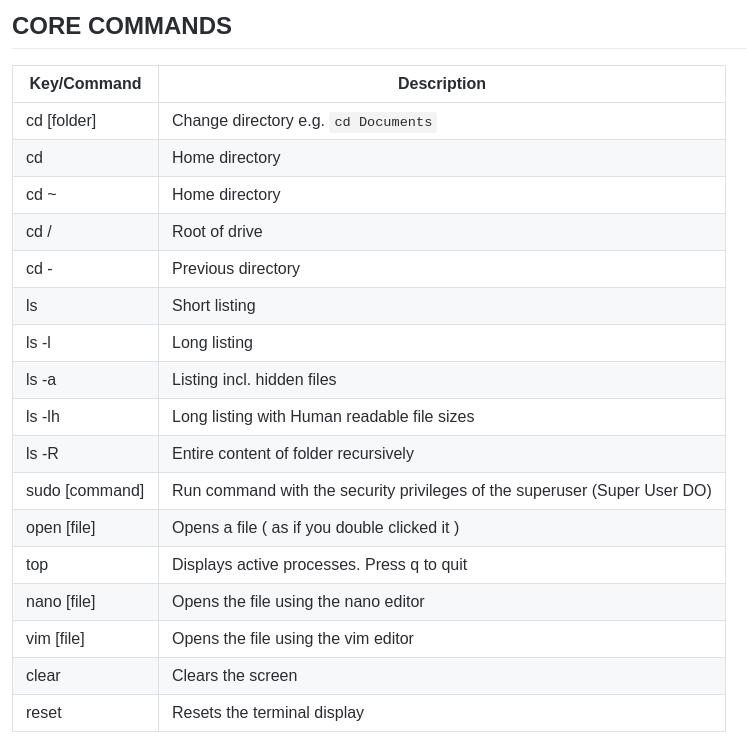
Sensor IoT Workshop - Light
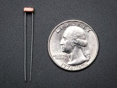
Photo resistor (Light Sensor)
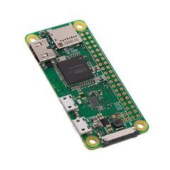
Minimal Set-up
-
RPI plugged into a Power Supply
-
Light sensor (LDR Sensor)
-
1uF Capacitor
For many basic projects or products that need to detect when a person has left or entered the area, or has approached, PIR sensors are great. They are low power and low cost, pretty This photoresistor is yet another sensor that I will be looking at incorporating into future projects such as a light activated alarm clock.
I explain a bit further down each of the parts that I will be using in this circuit. Be sure to read up on it if you need more information on these.
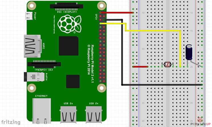
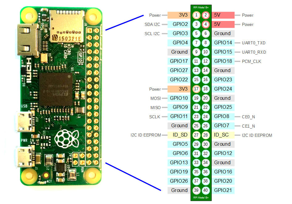
It is important to note that for this tutorial I am just using a simple photocell sensor while these are perfect for some tasks they might not be as accurate as you would like. To get the light sensor circuit built correctly follow the steps below or check out the circuit diagram right underneath the steps. In the following steps, I am referring to the physical numbers of the pins (Logical order).
-
First, connect pin #1 (3v3) to the positive rail on the breadboard.
-
Next, connect pin #6 (ground) to the ground rail on the breadboard.
-
Now place the LDR sensor onto the board and have a wire go from one end to the positive rail.
-
On the other side of the LDR sensor place a wire leading back to the Raspberry Pi. Hook this to pin #7 (GPIO4)
-
Finally, place the capacitor from the wire to the negative rail on the breadboard. Make sure you have the negative pin (the shorter leg) of the capacitor in the negative rail.
This python script will read from GPIO pin 4 and print the input to the Terminal Copy the code below and save the file on your rpi ‘light-sensor.py’
#!/usr/local/bin/python

import RPi.GPIO as GPIO
import time

GPIO.setmode(GPIO.BCM)

#define the pin that goes to the circuit
pin_to_circuit = 4

def rc_time (pin_to_circuit):
    count = 0

    #Output on the pin for
    GPIO.setup(pin_to_circuit, GPIO.OUT)
    GPIO.output(pin_to_circuit, GPIO.LOW)
    time.sleep(0.1)

    #Change the pin back to input
    GPIO.setup(pin_to_circuit, GPIO.IN)

    #Count until the pin goes high
    while (GPIO.input(pin_to_circuit) == GPIO.LOW):
        count += 1

    return count

#Catch when script is interrupted, cleanup correctly
try:
    # Main loop
    while True:
        print rc_time(pin_to_circuit)
except KeyboardInterrupt:
    pass
finally:
    GPIO.cleanup()
Once we are logged into the Raspberry Pi using SSH we can run the script with the command
$ sudo python light-sensor.py
To do - Consider adding an LED to turn on when the light sensor is activated
refs Guide